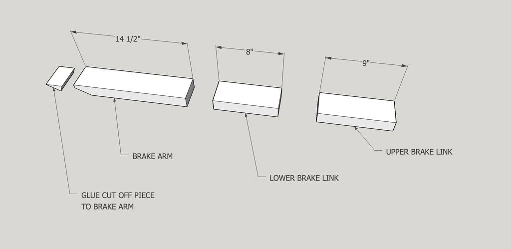
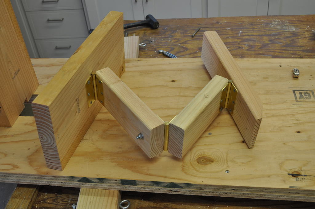
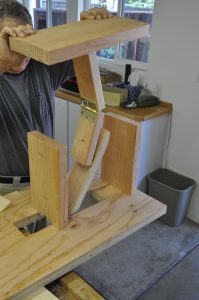
Cut three pieces of 2″ x 4″ 8′, 9″ and 14 1/2″ long. The 8″ and 9″ pieces will form the brake linkage and the 14 1/2″ piece is the brake arm. The arm and linkage assembly goes together as shown in figure sk-13 and is then fastened to the housing top as shown in figure 14.
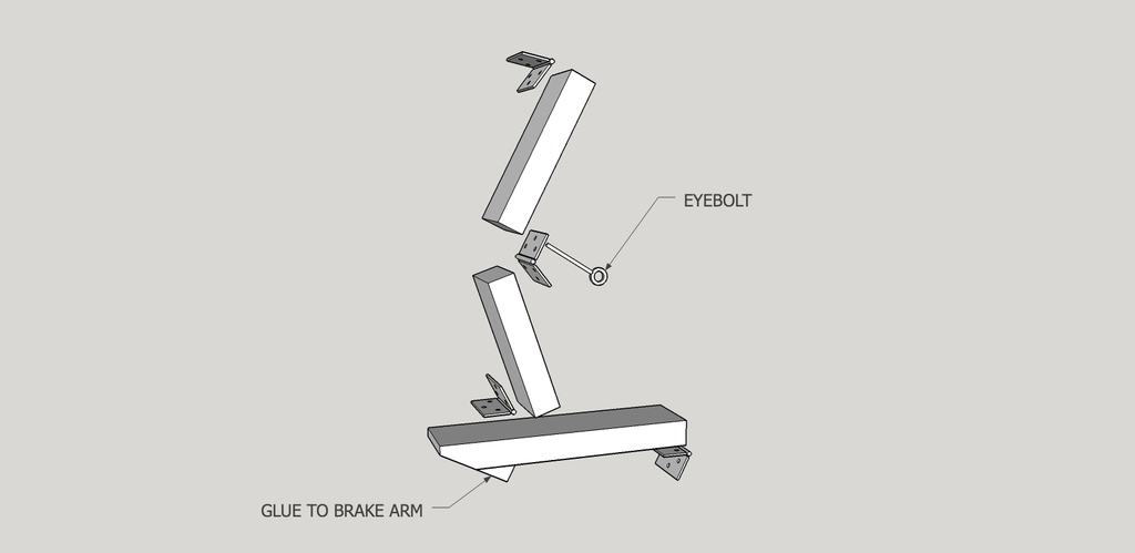
figure sk-13
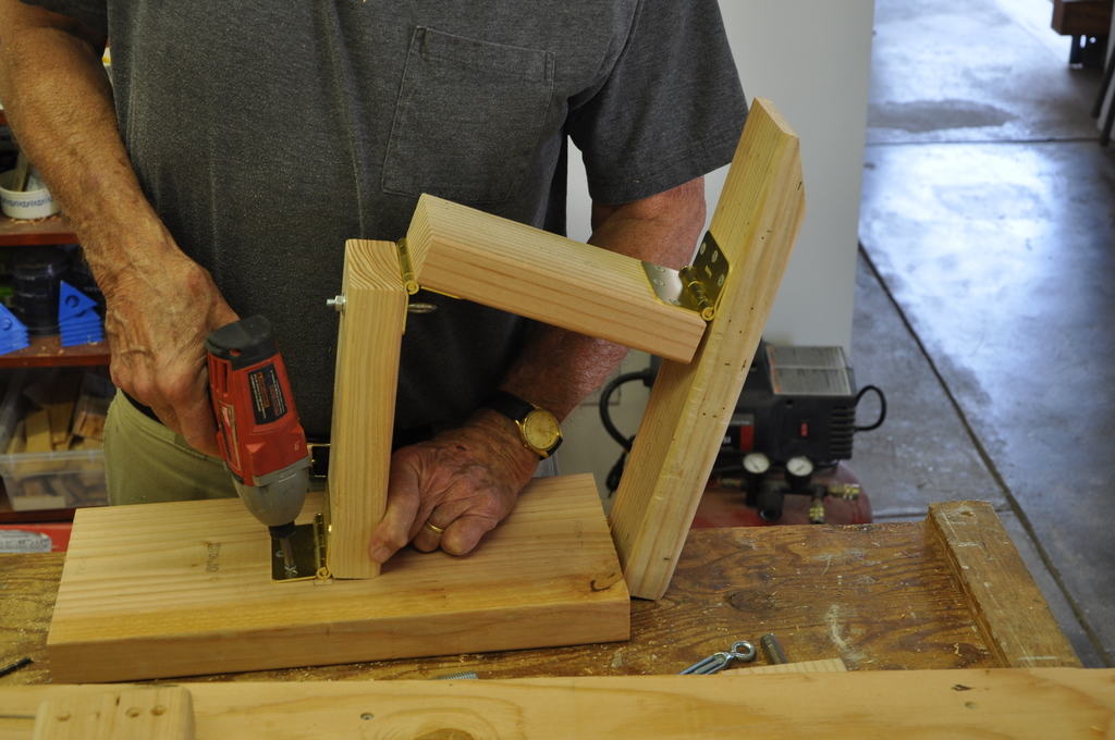
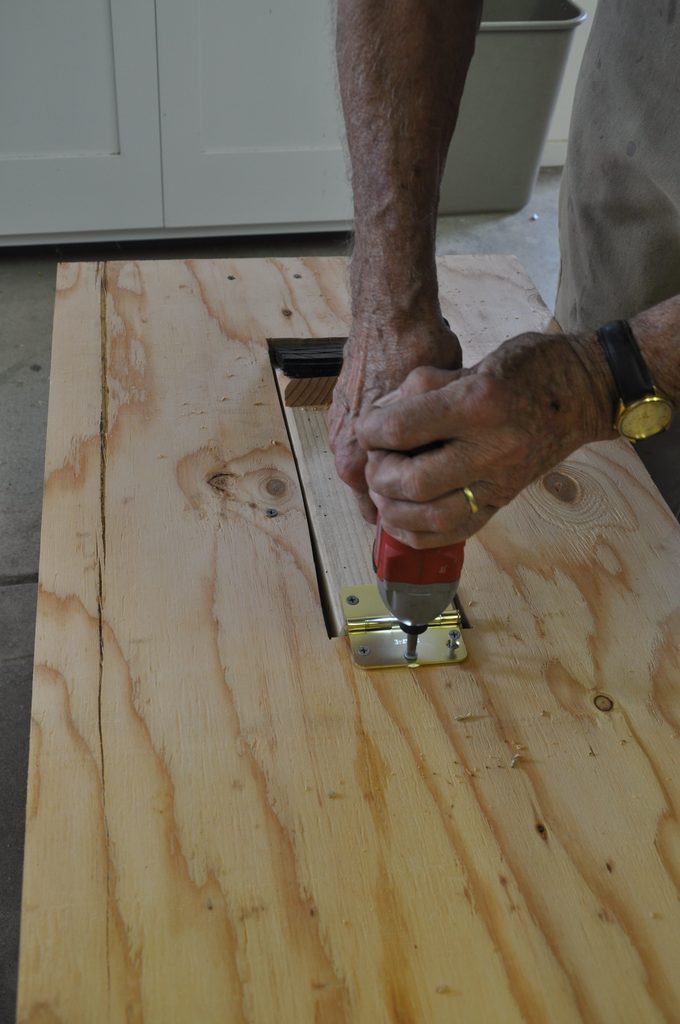
figure 14
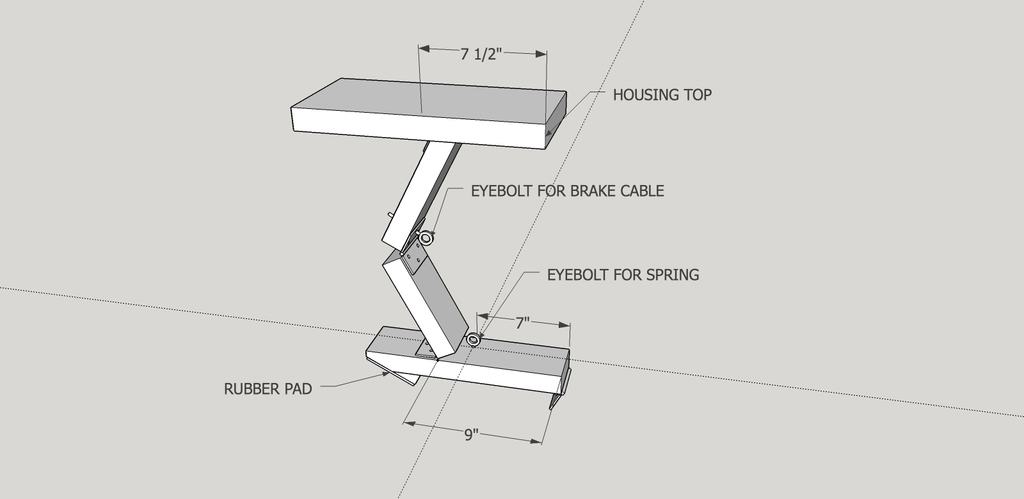
figure sk-15
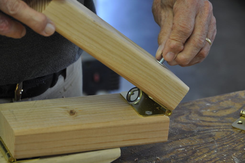
The brake arm, the upper and lower linkages and the brake housing top are joined together with hinges. The center hinge screw to the upper linkage is replaced with an eye bolt for the brake cable.
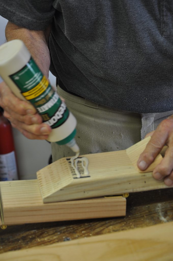
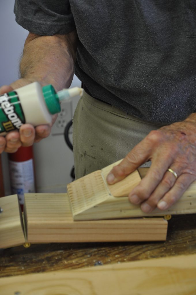
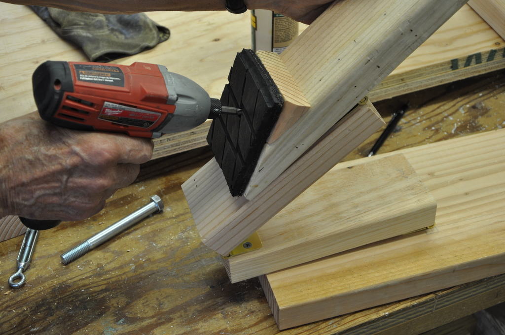
One end of the brake arm is cut at an angle, and the part that is cut off is glued back on the brake arm just behind the cut area. This forms the surface where the rubber brake pad is fastened.
 ,
,
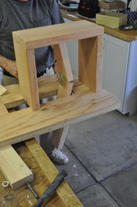
The brake arm linkage top assembly is lowered through the brake arm opening in the frame. The brake housing top is fastened to the two supports with lag bolts.
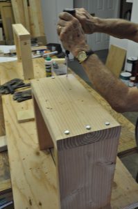
With the frame turned over, the brake arm is fastened to the frame with a hinge.